National toll-free hotline
0755-89785254
National toll-free hotline
0755-89785254Centralized power generation is undergoing an innovation. Traditional power plants (such as coal, gas and nuclear) are gradually being replaced by renewable, decentralised solutions (such as wind, solar or biomass). The latter often follow the same principle, which is to use renewable energy (solar, wind, and biomass) and generate either dc or ac voltages or currents through one or more conversion processes. Because energy producers are dispersed, more and more energy is fed not into high-voltage power systems but into medium-voltage and low-voltage systems. Therefore, in the future, it will be more and more necessary to adopt intelligent power system management of energy storage devices to meet the peak load demand in a variable way. The core components of these plants are power converters that provide the generated energy to the power system or consumers in a synchronous manner and of the right quality. Not only do these plants impose extreme requirements on the components, but they must also achieve a service life of about 20 years under harsh environmental conditions.
In recent years, the development focus of power converters has shifted to higher power density and higher switching frequency of semiconductors. The first development makes it possible to improve the cost performance by increasing the output power while keeping the system cost almost unchanged. The second development increases system efficiency because system losses are reduced as switching frequencies increase.
Conceptual circuit diagram of power converter
Conceptual circuit diagram of power converter
The power converter moves from the input side of the circuit (left) to the consumption side (right) and has a resistor (RI) to limit the charging current to protect the capacitor against interference. When energized, the resistor must receive a large amount of pulse energy. This energy flow or application of energy occurs within a very short period of time of capacitive charging, and usually only once (occurs during start-up and is not periodic). This places special requirements on the resistance technique used. The adiabatic boundary condition exists because of the short duration of the pulse. Therefore, this energy is applied only to the acTIve material of the resistance, and is not propagated throughout the resistance by heat conduction.
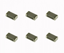
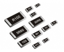
Compared with thick film or film technology, the winding resistance has a large effective mass and can therefore accommodate high pulse energy and continuous power. But low power converters use all resistance techniques. These include smd-melf film resistance, LTO thick film resistance and the winding resistance mentioned above. If the power is high, the winding resistors in series or parallel can be combined into printed circuit board (PCB) components (G200, AC, RS, CW, FS, and Z300). There are a number of special winding resistors (such as GWK, GWS, CSxx, FST, FSE, EDGx, RSO, and GBS series) or thick film resistors (such as LPS or RPS on radiators, which can be installed away from the PCB due to an extremely wide range of connection options) available when power exceeds 50 W.
After the ac voltage is converted to a suitable voltage level, the ac voltage is adjusted using the B6 bridge and then the inductance is used to suppress interference. On the one hand, the series of DC link resistor (RDC) and DC link capacitor is used to limit the charging current of DC link capacitor. This current produces a relatively high but infrequent pulse load. On the other hand, the series is used to suppress harmonics in the DC link circuit, which are equal to a continuous load (because of the continuous repetition of the pulse train). Therefore, the resistance used must be limited to withstand continuous power and pulse power.
The latest power converters have the option of providing capacitive or inductive reactive power to power systems or power consumers. This is achieved by increasing or decreasing the voltage of the DC link circuit. This increase is achieved using an internal boost converter or directly at the input location of the power converter. The chopper resistance (RBR) is used to reduce the voltage of the DC link circuit by converting excess electrical energy into heat energy. Power MOSFET, IGBT module or thyristor provide resistance switch function.
The power MOSFET and IGBT modules can perform high frequency switching operations, but the thyristor only supports low frequency operation. These power switches connect the chopper resistance when the DC link circuit voltage is in danger of exceeding the specified maximum. After the DC link voltage drops due to this operation, the chopper resistance is disconnected again. These chopper resistors are simple to install, have a wide range of connection options, and have a power dissipation of 100 w-1000 W. This situation often find chopping resistance and lever resistance (crowbar resistor) combination. This combination makes it possible to fully dissipate the DC link's energy into the resistor (RBR) in the event of a downstream component failure, thus preventing power converter damage. Here can choose the main component of the steel grid or steel resistance. For these types of resistance, the extremely diverse alloy steel plates have ripple structures, which can be cascaded to set the resistance value, continuous power, pulse power, and maximum surface temperature as needed. Insulation between steel plates may be made of ceramic or mica materials. In addition, these sheet resistances have very low inductance, so no additional voltage spikes are generated during the switching.
Steel grid resistors (such as Vishay GREx) are suitable for high continuous power due to the natural convection cooling provided by their large surfaces or the use of fans. Maximum achievable heat loss in this case is limited only by available mounting space and fan output. However, if more power is required and less insulation space is required, a water-cooled resistor such as the Vishay WCR series can be used.
In addition to the limitations of transient input surge current, filtering, and matching of the described DC link circuit, the DC voltage is converted to ac voltage with variable frequency and pulse width by the H bridge circuit shown. The filter resistor (RHF) and the output capacitor in series are used to suppress harmonics at the output stage. In addition, RHF can also limit the charging current of the filter capacitor. Capped wound resistors (such as the GWK and FVT series) are suitable for filtering applications due to their ease of installation and their high pulse power and continuous power. This series of products is different in that its stable glass insulation has the property of wet-resistant and chemical-resistant cleaning materials. The GWK and FVT series can also easily achieve low inductance resistance. In this respect, there are two resistance wires in a double-stranded manner around the resistance body. According to the superposition principle, the counterrotating current causes the magnetic fields generated to cancel each other out.
Next up are pry bar resistors (RCR) -- if they haven't been put into the DC link yet. As mentioned earlier, the purpose of this resistance is to prevent overload of the surrounding components in the event of a failure.
The three resistors, RDC filter resistor, RBR chopper resistor and RHF filter resistor, are of great help to optimize the efficiency of the optimized system. In the case of high speed switching elements (such as IGBT or power MOSFET), it is necessary to carefully design these resistors to achieve low inductance. Incorrect resistance selection may result in a resonant circuit due to parasitic inductance and capacitance. These circuits can generate peak voltages that overload or damage semiconductor components. In addition, the parasitic inductance "circulates" the signal waveform, making it impossible to produce a rectangular pulse with a steep rise edge. In addition, it has a negative effect on the power and efficiency of the whole circuit.