National toll-free hotline
0755-89785254
National toll-free hotline
0755-89785254Patch resistance description
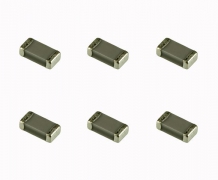
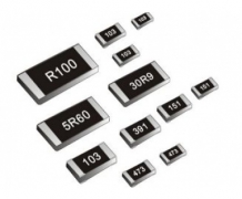
Chip resistors, Chip from Fixed Resistor directly translated, commonly known as SMD Resistor (SMD Resistor), is one of the metallic glass uranium Resistor. Is the metal powder and glass uranium powder mixed, using screen printing method printed on the substrate made of resistor. Moisture resistance, high temperature, low temperature coefficient. (note: the following chip type fixed resistors are called patch resistors)
Patch resistance classification
Patch resistors can be divided into the following categories:
Types refer to the international classification
Conventional series thick film patch resistors
General purpose General purpose, 0201-0805
General purpose, 1206-2512
High precision and high stability patch resistor
High precision - High stability, 0201-0603
High precision - High stability, 0805-1210
High precision - High stability, 2010-2512
Conventional series film patch resistors
General purpose thin film General purpose thin film, 0201-2512
Low resistance patch resistance
Low ohmic Low ohmic, 0402-1206
Low ohmic, 2010-2512
Patch resistance array
The Arrays Arrays, convex and concave
Patch current transducer
-sheldon: SMD is currently operating on a current, current, Low TCR
Patch network resistor
Network Network, t-type and l-type
Chip resistor package and size
Package and size of SMT resistor are shown in the following table:
Imperial (mil) metric (mm) long (L) (mm), width (W) (mm) (t) (mm) (mm) b (mm)
0.60±0.05 0.30±0.05 0.23±0.05 0.10±0.05 0.15±0.05
1.00±0.10 0.50±0.10 0.30±0.10 0.20±0.10 0.25±0.10
1.60±0.15 0.80±0.15 0.40±0.10 0.30±0.20 0.30±0.20
2.00±0.20 1.25±0.15 0.50±0.10 0.40±0.20 0.40±0.20
1.60±0.15 0.55±0.10 0.50±0.20 0.50±0.20
2.50±0.20 0.55±0.10 0.50±0.20 0.50±0.20
1812 4832 4.50±0.20 3.20±0.20 0.55±0.10 0.50±0.20 0.50±0.20
2.50±0.20 0.55±0.10 0.60±0.20 0.60±0.20
2512 6432 6.40±0.20 3.20±0.20 0.55±0.10 0.60±0.20 0.60±0.20
The relationship between chip resistance packaging and power
The encapsulation and power relationship of patch resistor is shown in the following table:
Package rated power @ 70°C maximum operating voltage (V) inch (mil) metric (mm) conventional power series lift power series
0201 0603 1/20w / 25
0402, 1005, 1/16w / 50
0603 1608 1/16w 1/10w 50
0805 2012 1/10w 1/8w 150
1206 3216 1/8w 1/4w 200
1210 3225 1/4 w 1/3w 200
1812 4832 1/2 w / 200
2010 5025 1/2w 3/4w 200
2512 6432 1W / 200
Note: voltage =√ power x resistance value (P=V2/R) or the smaller of the maximum operating voltage
Characteristics of patch resistors
· small size and light weight;
· adapt to reflow welding and wave soldering;
· stable electrical performance and high reliability;
· low assembly cost and matching with automatic mounting equipment;
· high mechanical strength and high frequency characteristics.
Naming method of patch resistor
Naming method of domestic SMT resistor:
1. Designation of 5% accuracy: rs-05k102jt
2. Designation of 1% accuracy: rs-05k1002ft
R - for resistance
S - means that the power of 0402 is 1/16w, 0603 is 1/10w, 0805 is 1/8w, 1206 is 1/4w, 1210 is 1/3w, 1812 is 1/2w, 2010 is 3/4w, and 2512 is 1W.
05 - dimensions in inches: 02 for 0402, 03 for 0603, 05 for 0805, 06 for 1206, 1210 for 1210, 1812 for 1812, 10 for 1210, 12 for 2512.
K minus means the temperature coefficient is 100PPM,
102-5% accuracy value representation: two significant figures, said before the third said how many zero, the basic unit is Ω, 102 = 10000 Ω Ω = 1 k. Said 1002 is 1% value representation: top three significant figures, the fourth said how many zero, the basic unit is Ω, 10 k Ω Ω = 1002 = 10000.
J - indicates accuracy of 5%, and F- indicates accuracy of 1%.
T - stands for braided packaging
The accuracy of resistance value error of patch resistance is ± 1%, ± 2%, ± 5% and ± 10%. The most commonly used ones are ± 1% and ± 5%.
Plus or minus 5% accuracy of routine is to use three digits to represent the cases of 512, in front of the two is a valid number, the third digit 2 said how many zero, the basic unit is Ω, this is euro 5100, 1000 Ω Ω = 1 k, 1000000 m Ω Ω = 1
In order to distinguish the resistance of ± 5% from ± 1%, the resistance of ± 1% is usually expressed in four digits.
The top three is the number effectively, the fourth said how many zero 4531 or 4530 Ω, Ω is equal to 4.53 K
Patch resistor selection
Surface assembly technology (SMT) has been widely used, with more than 90 per cent of electronic products assembled using SMT. SMT has been used in China since the 1980s. With the development of small SMT production equipment, the application scope of SMT is further expanded, aviation, aerospace, instrumentation, machine tools and other fields are also using SMT to produce a variety of small quantities of electronic products or components.
In recent years, in addition to electronics developers using patch devices to develop new products, maintenance personnel have also begun to repair a large number of SMT assembled electronics. This paper will introduce the main parameters and specifications of chip resistors, capacitors and inductors with the largest dosage, in order to help developers and maintenance personnel to choose these chip components.
At present, the model of SMT resistor is not uniform, set by each manufacturer, and the model is very long (composed of more than ten English letters and Numbers). When choosing, if you can correctly put forward various parameters and specifications of the chip resistance, it can be very convenient to choose and buy (or order) to the required resistance.
There are 5 parameters of SMT resistance, namely size, resistance value, tolerance, temperature coefficient and packaging.
1. Size series patch resistor series generally have 7 sizes, with two size code to represent. One size code is the EIA code represented by four digits. The first two and the last two represent the length and width of the resistance in inches. The other is metric code, also represented by four digits in millimeters. The power rating varies with the resistance of different sizes. The codes and power ratings for the seven resistance sizes are listed in table 1.
2. Series of resistance nominal resistance is determined by series. Each series is divided by the tolerance of resistance (the smaller the tolerance, the more the resistance is divided), the most commonly used of which is e-24 (the tolerance of resistance is ± 5%), as shown in table 2.
The resistance value is represented by three digit Numbers on the surface of the patch resistor, in which the first and second digit are significant Numbers, and the third digit is the number of zeros. The decimal point is denoted by "R" and occupies one significant digit. The nominal resistance code representation method is shown in table 3.
3. Tolerances of patch resistor (carbon film resistor) have 4 grades, that is, F grade, ±l %; Grade G, ± 2%; Grade J, ± 5%; Level K, plus or minus 10%.
4. Temperature coefficient the temperature coefficient of patch resistor has 2 levels, namely w level, ±200ppm / ℃. X level, ±lOOppm / ℃. Only resistors with an F tolerance are rated x, and resistors with other tolerances are rated w.
5. There are mainly two kinds of packing in bulk and ribbon roll.
The working temperature range of the SMT resistor is -55--+125℃, and the maximum working voltage is related to the size: 0402 and 0603 are 50V, 0805 are 150V, and other sizes are 200V.
Currently the most widely used size codes for SMT resistors are 0805 and 1206. And gradually has the trend to 0603 development. The most commonly used tolerance is J.